Instrument Deployment System (IDS)


mission specific
Introduction
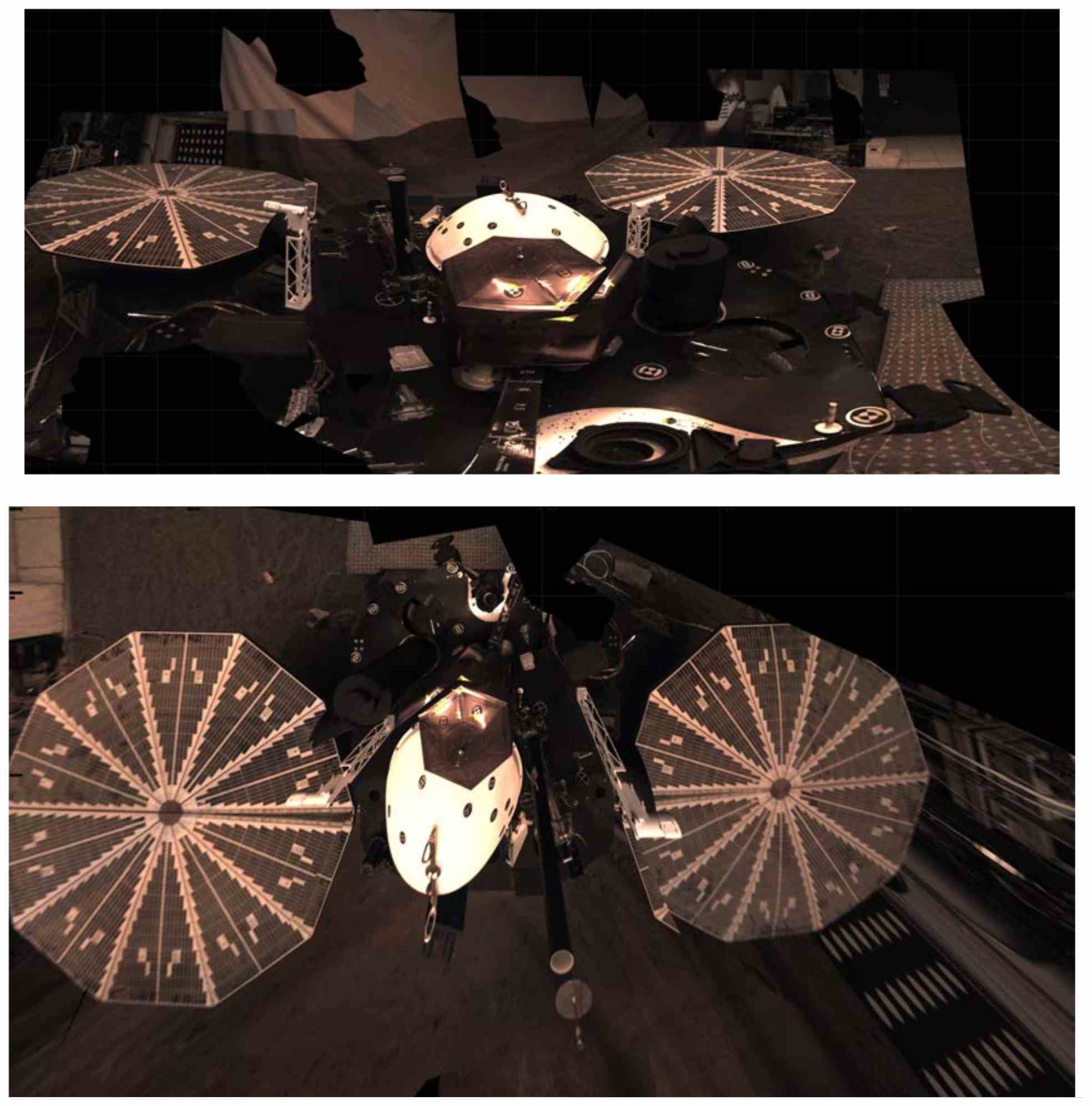
The function of the IDS is to place the instruments safely on the surface of Mars. The IDS (figure below) consists of four main components. The Instrument Deployment Arm (IDA) is responsible for placing the instrument packages on the surface and provides pointing for the Instrument Deployment Camera (IDC). The IDC is mounted on the arm and is used to image the work area in stereo for deployment planning and secondary geologic science of the area surrounding the Lander. The Instrument Context Camera (ICC) provides a wide-angle view of the entire workspace and provides a degraded functional back up to the IDC. The ICC is mounted at the bottom of the Lander’s deck, right underneath the base of the IDA. The last component is the IDS control software.
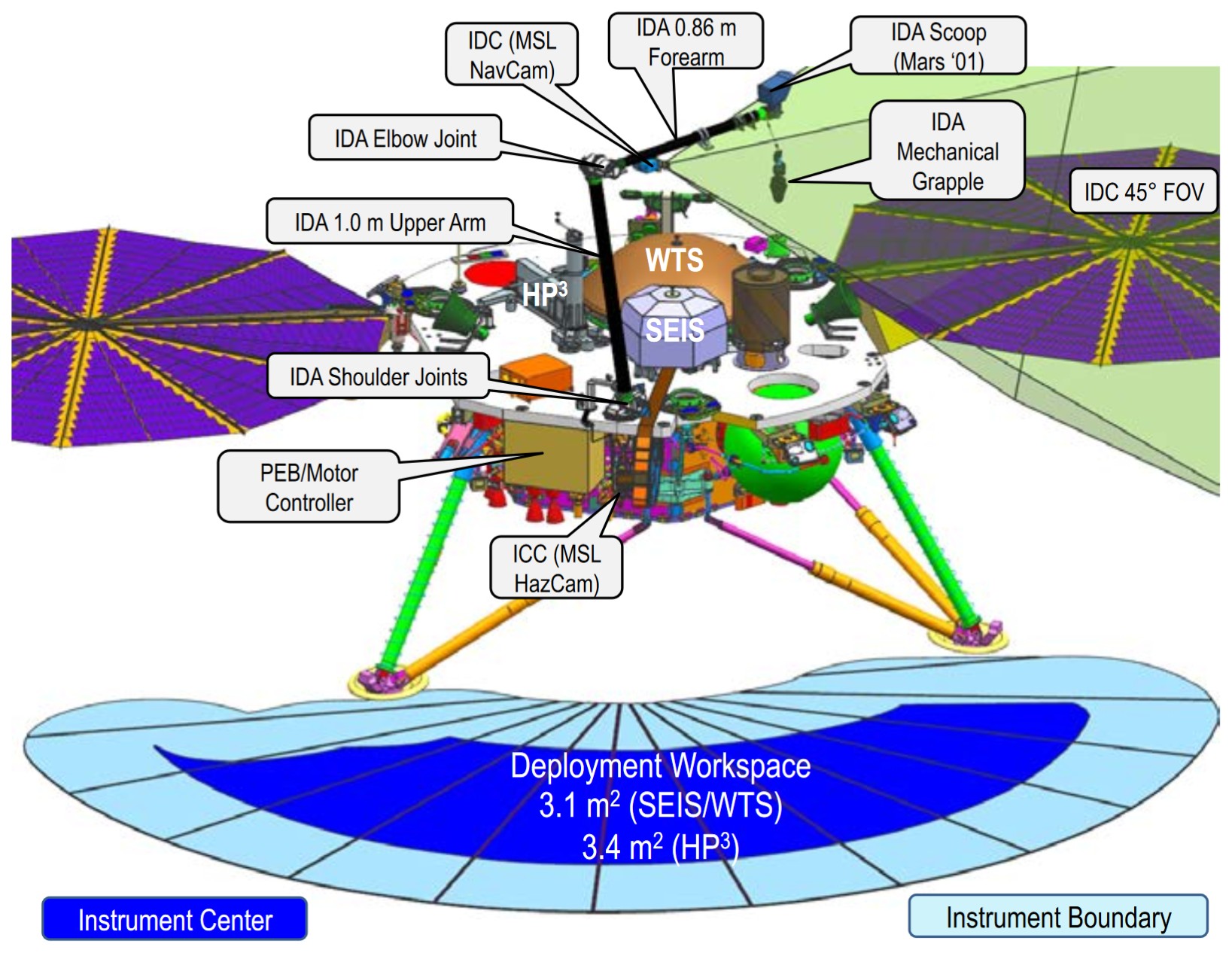
IDS before Instrument Deployment.
Instrument Deployment Arm (IDA)
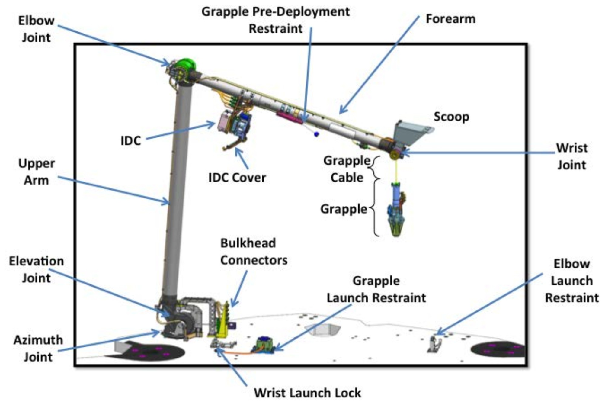
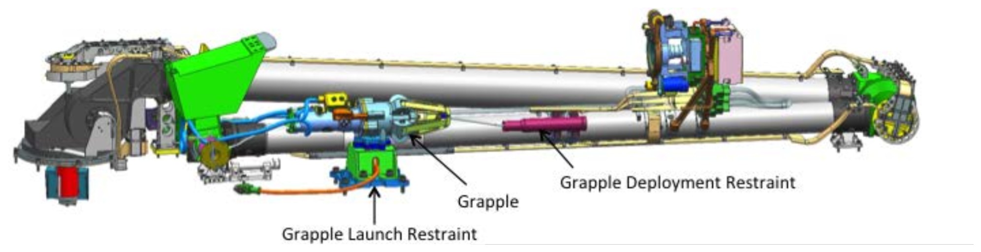
The IDA is the flight arm from the original Mars ’01 lander. The arm has been refurbished and rebuilt by JPL with some components replaced and delivered to LMA for integration onto the Lander. The various components of the IDA in deployed and stowed state are illustrated in the two figures below, respectively. The arm has been upgraded to include a mechanical grapple that will be used to pick up and deploy and place the instrument components. It preserves the scoop of the original Mars’01 arm with some modifications.
Deployed IDS Configuration Overview.
IDA and grapple stowed.
The IDA has four degrees of freedom (DoF). It can capture and retain deployable elements, including under loss of power, until placement on the surface is confirmed. It can lift a mass up to 9.5 kg and deploy elements to the surface with the Lander deck tilted up to 15 degrees with respect to gravity. The maximum deployment torque occurs when SEIS (9.5 kg) is placed at the farthest reach of SEIS/WTS workspace (179 cm from the IDA base). The IDA actuators performance (motor plus drive train) was characterized, leading to torque ratings at 20° C of about 26 (max continuous) and 46 (max peak) N- m for the azimuth joint, 91 and 146 N-m for the elevation joint, 53 and 86 N-m for the elbow joint, and 10 and 15 N -m for the wrist joint. The Grapple is in the field of view of the IDC during capture and disengagement from deployable elements.
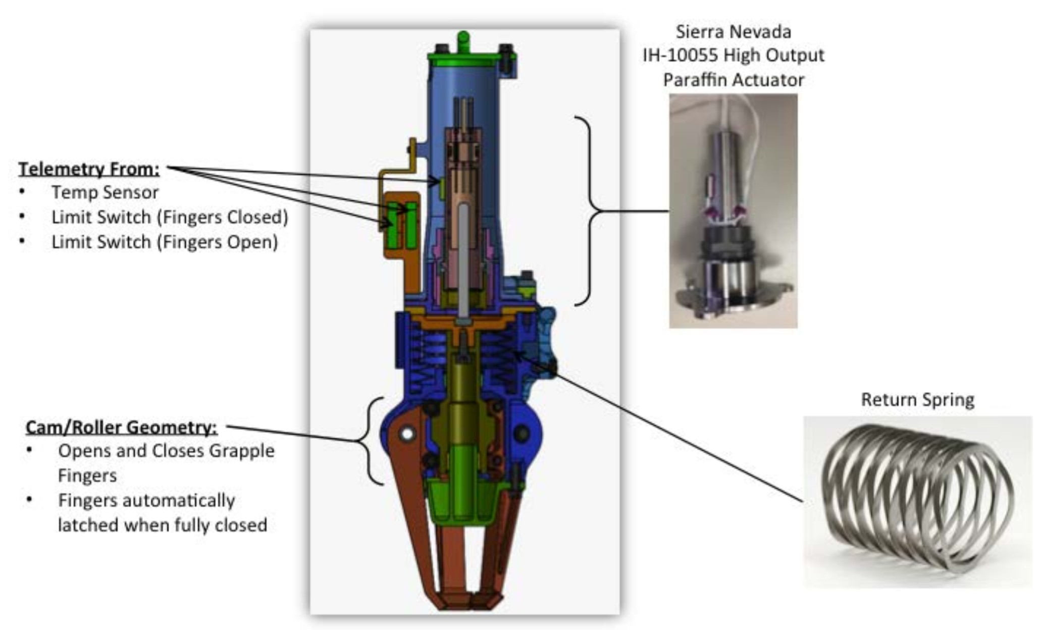
The grapple design is displayed in the first figure below. It hangs from the IDA such that its central axis is within ±1 degree with respect to the gravity vector. The grapple can engage the grapple hook on each deployable element (second figure below) with up to 15 degrees misalignment and up to 15 mm of positioning error. Its minimum load capacity of 143.2 N when not powered and with its finger closed over a grapple hook. The grapple can be re-stowed against the arm after instrument deployment, which would remove the deployed grapple from the images acquired by the IDC.
Grapple design.
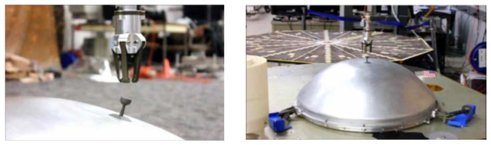
Image obtained in JPL’s IDS testbed of the grapple about to grab the WTS.
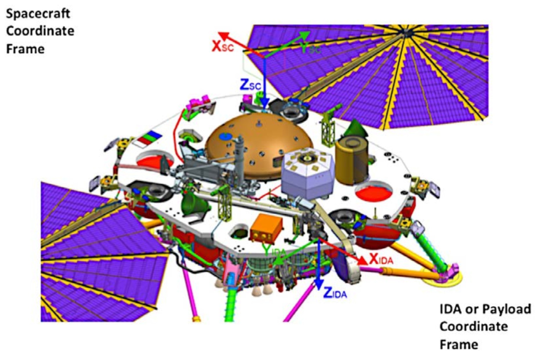
The grappleis manipulated by the IDA such that it can engage, pick up, and deploy SEIS, WTS, and HP3 to the Mars surface. The arm deploys the SEIS sensor head, WTS and HP3 with a surface touchdown velocity of no more than 2.5 cm/sec. The IDA positions the grapple with an absolute error of less than or equal to 0.015 m and determines the IDC imaging baseline to within 0.0028 m. The IDS has the necessary information to localize deployable elements on the surface to within sub-mm accuracy via fiducials on the deployed elements imaged using the IDC stereo pairs. The coordinate frame of the IDS is illustrated in the figure below.
(Top) Spacecraft coordinate frame and (bottom) IDA or workspace coordinate frame.
The grappleis manipulated by the IDA such that it can engage, pick up, and deploy SEIS, WTS, and HP3 to the Mars surface. The arm deploys the SEIS sensor head, WTS and HP3 with a surface touchdown velocity of no more than 2.5 cm/sec. The IDA positions the grapple with an absolute error of less than or equal to 0.015 m and determines the IDC imaging baseline to within 0.0028 m. The IDS has the necessary information to localize deployable elements on the surface to within sub-mm accuracy via fiducials on the deployed elements imaged using the IDC stereo pairs. The coordinate frame of the IDS is illustrated in the figure above.
Instrument Context Camera (ICC)
The ICC is a wide-angle color camera that is hard-mounted to the lander (see first figure in this topic). The primary purpose of the ICC is to provide contextual views of the entire deployment area during all phases of instrument deployment (see figure below). The ICC will acquire the first image of the workspace on Sol 0 and will continue to monitor the workspace throughout the pre- and post-deployment stages of the mission. The ICC will also provide a backup means of imaging the atmosphere for dust optical depth determinations to assist in power predictions. The ICC is a flight spare MSL Hazcam with an upgraded Bayer color filter array detector. The table below lists the main characteristics of the ICC.
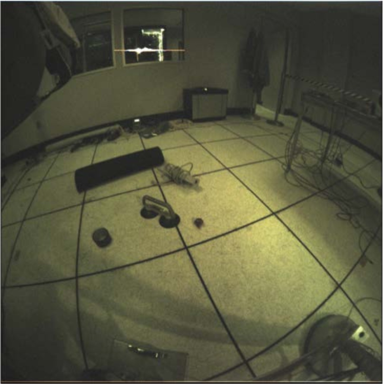
ICC image from the InSight testbed. The lander footpad can be seen in the lower right.
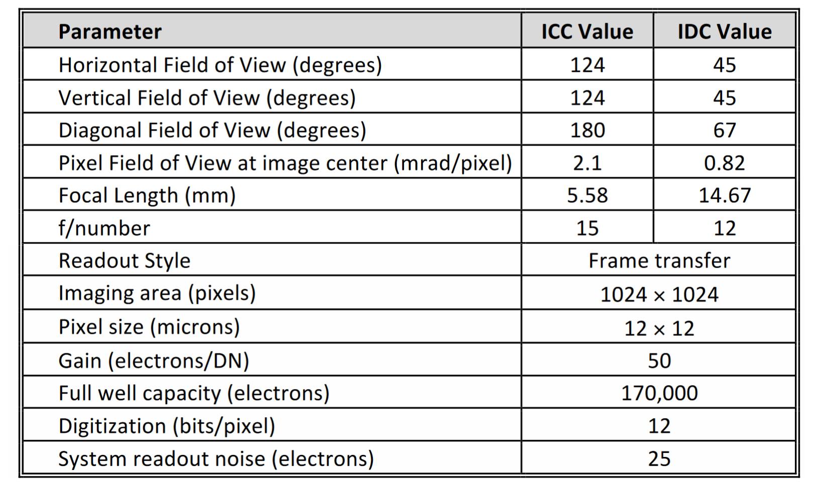
ICC and IDC camera parameters.
Instrument Deployment Camera (IDC)
The IDC is a narrow-angle color camera that is mounted on the forearm segment of the Instrument Deployment Arm (see the first IDA figure above). The main purposes of the IDC are to provide detailed stereo views of the deployment area and to verify arm interactions with the instrument hardware (e.g., grapple, lifting, and placement). The IDC will also acquire images of the sky; these images will be used to determine the dust optical depth in the Martian atmosphere as a primary input to solar panel power modeling. The IDC is a flight spare MSL Navcam. Like the ICC, the IDC has been upgraded with a Bayer color filter array detector. The table in the ICC section lists the main characteristics of the IDC.
After arm deployment, the IDC will image the lander feet, solar panels, payload deck, and deck fiducial targets (see the first figure below). The IDC will then be used to image the entire workspace in stereo at varying spatial resolutions; these images will be used to generate three-dimensional Digital Terrain Models (DTMs) of the deployment workspace (see the second figure below). Once the instrument placement sites are chosen, the IDC will image each site at a higher spatial resolution. During instrument deployment, IDC confirmation images will be acquired of the pre-grapple positions, grapple engagements, lifts, placements, and release of the instruments. A final IDC stereo pair will document the actual placement of the instruments. IDC stereo imaging of the SEIS instrument head assembly after placement and disengagement will also be used to determine its orientation (azimuth) on the surface. Although not required for instrument placement, the IDC will likely be used to acquire a 360-degree panorama of the landing site as well as other images of the surface and atmosphere.
(Upper) Lander horizontal IDC mosaic and (Lower) Lander vertical IDC mosaic.
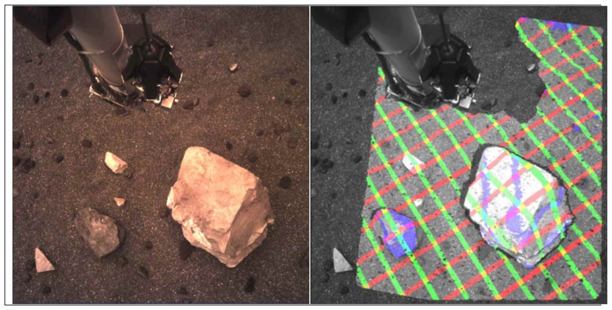
IDC image acquired in the Insight testbed (left). Corresponding 3-dimensional terrain shown as X (green), Y (red), and Z (purple) contours (right).
For more information on the IDC (Navcam) and ICC (Hazcam) hardware, see Maki et al. 2003 and Maki et al. 2012. Additional information on the MER/MSL camera hardware can be found in Bell et al. 2003 and Herkenhoff et al. 2003.
IDS science
Although the IDS primary function is instrument deployment, a variety of scientific investigations can be carried out using the arm and/or cameras (see for example Arvidson et al. 2009 for experiments conducted with the arm on the Phoenix mission). Observation of the sky to derive atmospheric tau is one task that benefits both science and engineering through its affect on solar power. Additional investigations will be considered if they do not jeopardize instrument deployment and if resources such as power, downlink, and operations staff are available. For this reason, investigations based only on use of the arm, such as for soil mechanics, or imaging beyond the deployment phase (with the exception of tau measurements, which would not require arm movement) are not likely to be successful.
see also